Losses Caused by Fringing Flux in Magnetic Core Transformers
Losses Caused by Fringing Flux in Magnetic Core Transformers
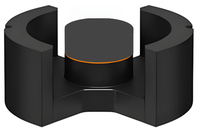
It’s worth noting that to effectively reduce the external residual magnetomotive force (MMF), a copper strip can be wrapped around the gap section, as shown in the figure above. This forms a shorted turn around the outer legs. When the core attempts to radiate any flux outward, if it links with this external shorted turn, a current is induced in the shorted turn. This current generates a magnetic field that counteracts the leakage of stray flux.
For EC cores, the cross-sectional area of the center leg is less than the sum of the cross-sectional areas of the outer legs. If gaps are added to both the center leg and the outer legs, the gap length in the outer legs should be reduced proportionally based on the cross-sectional area ratio between the center and outer legs. However, since this ignores core permeability and fringing flux effects, the gap lengths must be adjusted experimentally to achieve optimal results.
Core Issue Summary
Requirement An air gap is necessary to reduce the magnetic reluctance of the circuit and prevent saturation. The winding should be placed as close as possible to the gap (on the leg containing the gap).
Conflict: The air gap edge generates intense, spreading fringing flux.
Consequence: Turns of the winding exposed to this strong fringing flux field (especially those near the gap) experience very high eddy current losses when subjected to large flux swing amplitudes (ΔB), potentially leading to localized overheating or even winding burnout.
High-Risk Applications: Flyback transformers and Boost inductors operating in Discontinuous Current Mode (DCM) (where ΔB at full load is very large). The problem is less severe in filter inductors or any inductor designed for Continuous Current Mode (CCM) (where ΔB is small).